4.2. Getting started
In this chapter, we often refer to two example model files:
water.zml: a model of a single water molecule.dimer.zml: a dimer of tetrahydrofuran (THF) molecules}}
4.2.1. Installation
The installation of Zeobuilder is discussed on a separate page: Installation.
4.2.2. Starting Zeobuilder
Note
Windows users should first login to a Linux machine where Zeobuilder is installed with an SSH terminal client. Also make sure your XServer is running and configured properly.)
Zeobuilder is started by typing the zeobuilder command in the terminal.
One can start Zeobuilder without arguments:
zeobuilder
The Zeobuilder user interface pops up and the initial model is empty. Optionally one can also pass the filename of a model as the first argument, e.g.
zeobuilder water.zml
Now the model is initialized with the contents of water.zml as shown in the
figure below.
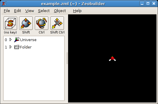
Zeobuilder showing the contents of water.zml
4.2.3. The Zeobuilder GUI
The main window of Zeobuilder consists of four major parts, indicated in the figure below:
Menu bar: The menu bar on top of the window gives access to all the features in Zeobuilder that do not require much user interaction. Some of these function ask for parameters first, but then continue autonomously.
3D view: The big area in the bottom right of the window is the 3D visualization of the molecular model. In the remainder of the tutorial, we name it the ‘3D view’. Interactive functions are performed by clicking and dragging in the area with the left/middle/right mouse button, optionally holding some modifier keys pressed.
Toolbar: The four toolbar buttons in the top left of the window define which interactive function in the 3D view is associated with each combination of modifier keys. The default settings for these buttons are
- (no key): Selection picker
- Shift: Translate
- Ctrl: Rotate
- Ctrl+Shift: Translate rotation center
The interactive functions will be discussed in more detail below.
Tree view: Below the toolbar, one finds the tree view that visualizes the tree representation of the model.
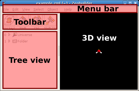
The four major components of the Zeobuilder main window.
4.2.4. The anatomy of a Zeobuilder model
The goal of this section is to recognize and select several parts of the model.
Open the model water.zml in Zeobuilder. Two objects are
visible in the tree view at the left of the window. The first object Universe
is the global reference frame that contains the molecule. The second object is a
folder that contains auxiliary data that is not visualized in the 3D view. It is
most practical to maximize the Zeobuilder windows now. (The screen shots are
kept small however.)
Click on the small triangle at the left of to the universe object in the tree
view. One sees that the Universe object acts as a Container that holds three
atoms (two oxygens and one hydrogen), and two bonds. The folder contains a
Notes object. Each bond has two references, one for each atom of the pair it
connects. A fully unfolded tree view is shown in the figure below.
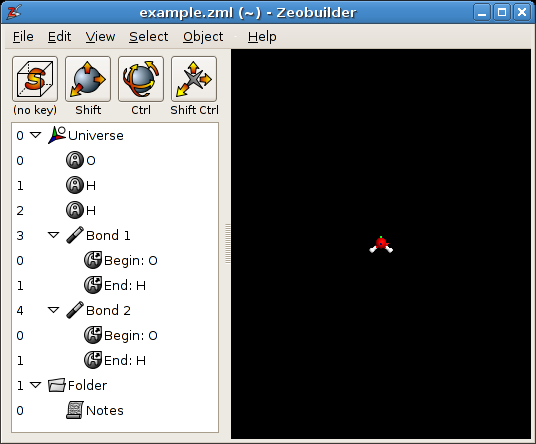
Zeobuilder showing the contents of water.zml. The whole tree is unfolded.
A single click on an object in the tree view selects that object. A double click activates the default action associated with the object. For most objects the default action pops up a dialog window in which one can inspect and edit the properties of that object. For reference objects, the default action is to select the target object.
4.2.5. Tree structure terminology
This tutorial specifies several aspects and properties of the tree structure with a dedicated vocabulary. Here is a list of terms that are often used in this context.
- Node
- Each element in a tree structure is a node. There are two basic types of nodes: references and objects.
- Reference
- A node that refers to an object. For example, a bond objects contain two references to atom objects.
- Object
- A node that is not a reference, e.g and atom or a frame.
- Parent and Child
- These two terms describe the relative hierarchy of nodes in a tree
structure. They are best explained on the basis of examples. In the water
model, the oxygen atom is a child of
Universe. Consequently,Universeis the parent of the oxygen atom. - Root node
- A root node has no parent nodes, i.e it is located in the highest level of
hierarchy in the tree structure. In Zeobuilder the
Universeand theFolderobjects are always the two only root nodes. - Super parent and Sub child
- Super parents and sub children are more generic types of parents and
children. For example, the bond objects the water model contain two
references each. The
Universeobject is a super parent of these reference objects, while the references are sub children of theUniverseobject. The concepts ‘Super parent’ and ‘Sub child’ relate nodes that are separated by one or more hierarchical levels, while the ordinary ‘Parent’ and ‘Child’ only apply to consecutive levels of hierarchy. The ordinary ‘Parent’ and ‘Child’ are sometimes also called ‘Direct parent’ and ‘Direct child’ for reasons of clarity. - Container
- An container object can contain child objects, e.g.
Universeis a container. A bond object is not a container because it only has references as children. - Common parent
The common parent of a set of objects satisfies two conditions:
- All the objects in the set are sub children of the common parent, i.e. the common parent is a super parent for all objects in the set.
- The common parent has no children that also satisfy the first condition. This means the following: In principle there can be multiple super parents that are common to all objects in a set. The common parent is the one with lowest hierarchical level.
4.2.6. Selections
There are three different techniques to select parts of the model. The current selection is always visualized in the tree view and the 3D view. The selections in both views are always synchronized.
- Click on an object to select it. The previous selection is forgotten.
- Click on an object while holding the control key to add (remove) the object to (from) the current selection.
- Click on an object while holding the shift key to select a range of objects.
4.2.7. Selections in the 3D view
Selecting objects in the 3D view is somewhat different, mainly because we want to make efficient use of all possible modifier keys and mouse button combinations. By default, mouse operations in the 3D view (without modifier keys pressed), modify the current selection. These are the rules:
- Click with the left mouse button (on an object) to set the current selection. The previous selection is forgotten.
- Click with the middle mouse button to add an object to the current selection.
- Click with the right mouse button to remove an object from the selection.
Instead of just clicking on an object, one can also draw a rectangle by dragging the mouse while one of the three buttons is pressed. All objects inside the rectangle are affected.
4.2.9. The relevance of making proper selections
In the remainder of this tutorial, we will go through the basic operations in
Zeobuilder. Not all operations are applicable to all selections. For example,
one can not delete the root objects. If one looks up the delete function in the
menu (Edit -> Delete) when no proper selection is made, the Delete function is
grayed out.
Note
Through observation we learned that the average user has the tendency to make all selections in the 3D view. In many cases, it is much easier to make a selection in the tree view. In the beginning it might be instructive to think before making a selection.
4.2.10. Adding and removing objects, fixing mistakes
From now on we will continue with the THF dimer model (dimer.zml). A screen shot is given in figure below. The model
contains three reference frames. The global reference frame is called
Universe, while the two THF molecules also have their proper (relative)
reference frames.
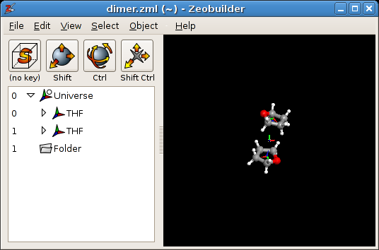
Figure A2.4: Zeobuilder with dimer.zml.
Click in the tree view on the first THF reference frame and press the Delete
button on your keyboard. It is gone! One can revert this (and any other)
operation with the undo function: Edit -> Undo (Ctrl-Z). The undo function
itself can be canceled with Edit -> Redo.
Now select the Universe object. Add a box object with Object -> Add -> Box.
The new object is placed at the origin of the
selected reference frame. In the sections below, we will explain how the box can
be translated to another position. It is also instructive to add a second box to
the reference frame of the first THF molecule: Select this frame in the tree
view and activate Object -> Add -> Box. Although both boxes have the same
translation vector [0,0,0], they have a different position in space because
their parents are different reference frames. To inspect the translation vector
of a box, select the box and activate Object -> Properties.
Finally we will connect the two oxygen atoms by an arrow. Select only the two
oxygen atoms and activate the menu function Object -> Connect -> Arrow. Keep
this arrow for the remainder of this chapter. It can be used as a rotation axis
in the next section.
4.2.11. Default units
Internally, Zeobuilder represents all aspects of the model in atomic units.
However, when numbers are displayed on screen, or when input is required from
the user, Zeobuilder will make the necessary conversions to/from the units of
choice. One can set these preferred default units via the menu function Edit ->
Configuration.
Note
It is a good idea to set your favorite default units at this point in the tutorial.
4.2.12. Rotations and Translations
There are two ways to perform transformations (on objects) in Zeobuilder. One can use the interactive rotation and translation tools, or one can use the functions from the menu. In both cases, one optionally introduces assisting objects that will define or limit the transformation.
4.2.12.1. Interactive translations
All interactive translations are activated by pressing the shift key while dragging with the mouse cursor in 3D view. The left mouse button will cause translations parallel to the projection plane of the viewer, the right button will translate orthogonal to this plane. There are two types of interactive translations:
- When one object is selected, this object will be translated.
- In all other cases, the whole model will be translated. Actually this is implemented by a translation of the viewer position in the opposite direction.
Just try these interactive translations to move around the THF molecules.
4.2.12.2. Interactive rotations
Interactive rotations are similar to interactive translations. They are activated with the control key instead of the shift key. The left mouse button is associated with rotations about an axis parallel to the viewer projection plane. The right mouse button activates a rotation about an axis orthogonal to the viewer plane. There are four types of interactive rotations:
- When only one object is selected, this object is rotated about its center/origin
- When one object and an additional point-like object is selected, the second selected object serves as rotation center. The order of the selected objects matters! Nearly anything can serve as a rotation center: atoms, spheres, boxes, other reference frames, ...
- When one object and an additional vector-like object is selected, the vector object serves as the rotation axis. First select the target object to be rotated, then select the rotation axis. Bonds, arrows and springs are all vector-like objects.
- In all other cases, the whole model is rotated, but again this is actually implemented as a rotation of the viewer in the opposite direction. The rotation center is defined by the small grey cross in the 3D view.
Try all these types of rotations on the THF dimer model. Have fun! Try to be creative! It also instructive in the end to press Ctrl-Z several times and to see how all your experiments are performed in reverse order!
4.2.12.3. Non-interactive transformations
All the interactive transformations have their non-interactive counterparts in
the menu (see Object -> Transform). The workflow is similar to the
interactive transformations:
- Select the target object to be transformed.
- Optionally select assisting points/vectors that define rotation center, translation vector, rotation axes, ...
- Activate the desired function from the menu. This will show a dialog window (in most cases), where one enters the transformation parameters. When one works with assisting objects, some of these parameters are filled in automatically.
- Hit the OK button and enjoy the result.
Note
The sub menu Object -> Transform hosts much more types of transformations than ordinary rotations and translations. Try them! Most functions are self-explaining.
4.2.13. Moving the global rotation center, zooming in and out
The global rotation center is the small grey cross in the center of the 3D view. It can be obscured by other objects. This point in space serves as a rotation center when the whole model is rotated with the interactive rotation tool, e.g. when no objects are selected. One can translate this point by dragging with the left mouse button in the 3D view while holding the control and the shift key pressed.
The scale at which the molecules are drawn can be changed by zooming in and out. Hold the control and shift key pressed while you drag with the right mouse button from the left of the 3D view to the right of the 3D view. The effect is that the viewer zooms in to the center of the 3D view. When dragging in the opposite direction, one zooms out.
4.2.14. Configuring the interactive functions
Until now, we gave the impression that the control key is always associated with an interactive rotation, and similarly all other combinations of modifier keys have a fixed meaning. This is not the case! Each button in the toolbar shows which interactive function is associated with which modifier key(s). When one clicks such a button, a popup menu offers the list of all existing interactive functions. (See figure below.) The selected function from this popup menu will become associated with the corresponding modifier key(s).
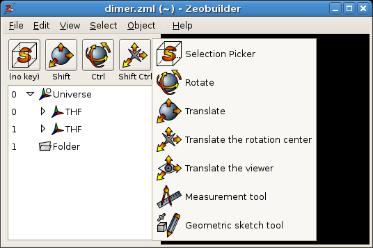
The popup menu that offers all interactive functions.
4.2.15. Changing properties of objects
This topic has been discussed previously, but we need to make a few additional remarks:
- One can always inspect/edit the properties of the selected object with the
menu function
`Object -> Properties`. - When multiple objects are selected, this menu function pops up a similar
dialog, but only those properties are shown that exist in all the selected
objects. For example, when a sphere and a box are selected, the color is a
property that both objects have, and consequently the color property will be
shown in the
Properties dialog. The quality property is only defined for a sphere, it will not be shown because the box does not have a quality property. When a property is set to a new value, all the selected objects are updated. This is useful, e.g. when changing the atom-type of many atoms.
4.2.16. Cut, Copy, Paste and Duplicate
The cut, copy, paste and duplicate functions work in the same way as any other regular editor program, e.g. a conventional word processor. The paste function in Zeobuilder works only when a reference frame (or another type of container) is selected where the pasted objects can be added.
4.2.17. Loading and Saving files
The menu functions File -> Open, File -> Save and File -> Save
as are again similar to those in conventional editors of any kind. Zeobuilder
supports three formats for loading files: .xyz, .pdb and .zml. Four
file formats are supported for saving files: .xyz, .pdb, .psf, and
.zml. The .zml format is the internal format of Zeobuilder.
Note
- Loading psf files is not supported in Zeobuilder because a psf file only contains topology information and no atom coordinates.
- ZML stands for ‘Zeobuilder Markup Language’. This file format is based on the XML standard. XML offers the advantage that one can design formats that will be forward-compatible with future versions of Zeobuilder, even when new types of model objects are introduced.
4.2.18. Import and Export
The File menu also contains an Import and an Export function. The Import
function loads a model from disk into the current model, without replacing the
current model. This is a handy tool to collect several molecules in one model.
The Export function does the reverse: It saves only the selected part of the
model in a file. The Export function is only applicable when some objects are
selected.
4.2.19. Concluding remarks
Congratulations! You reached the end of this chapter. Time for a coffee break! Before you run away from your computer, here are some practical advices:
- During your first Zeobuilder experiences, the interactive functions will be hard to handle. It will take some exercise before you fluently move around molecules and browse through your model. In the end you will be surprised by the practical default settings for the interactive functions. You will only rarely need to click the toolbar buttons.
- When using the 3D view to select all objects in the model by drawing a rectangle around them, one really selects everything, including the global reference frame. This might not always be what one expects. Make sure you understand what you are doing.