5.3. Constructing tubes
This chapter demonstrates the tube generator in Zeobuilder. It is a generic tool that converts a two-dimensional (flat) molecular system into a tube-shaped periodic or aperiodic system. It can be used to generate carbon nano-tubes, but we will also demonstrate how it can be used for other kinds of (hypothetical) tubes. It might be instructive to refresh your background on nanotubes.
5.3.1. The carbon nanotube
The tube tool is relatively simple to use, so we immediately kick of with an example:
- Load the model
graphite_sheet.zml. This is a two-dimensional periodic model of an infinite and flat graphite sheet. - Select the global reference frame.
- Activate the menu function
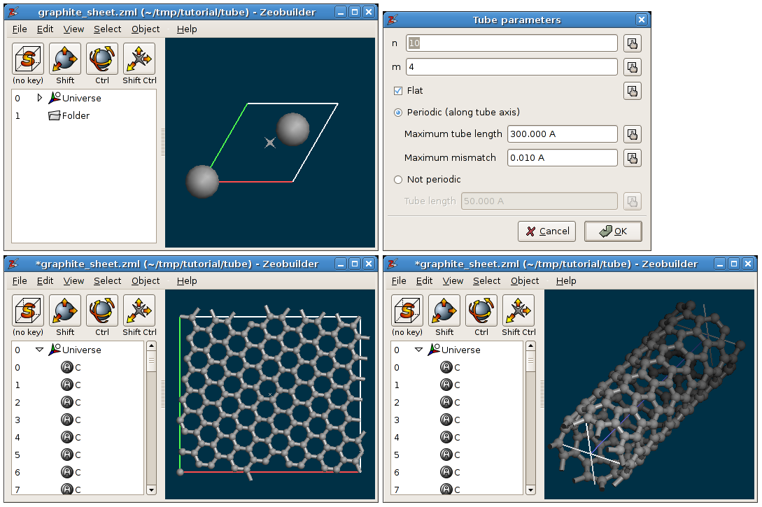
Object -> Builder -> Create tube. A Popup dialog appears that looks like the top left window in the figure below. Several parameters have to be entered:- The parameters n and m define the chiral vector of the tube.
- When the flat option is checked, the extended graphite sheet is not folded into a tube.
- The tube tool can create periodic tubes, but it is hard to control the length of periodic tubes for certain combinations of n and m. Aperiodic tubes on the other hand, can be easily generated with a prescribed length.
ClickOK.
- Now we can safely add bonds to the model:
press Ctrl-B.
An example of a carbon nanotube is presented in the figure below. Experiment with different parameters for the tube tool.

Carbon applications of the tube tool. TOP-LEFT: The orignal model, a minimal two-dimensional unit cell of a graphite layer. TOP-RIGHT: The dialog window with the tube parameters. BOTTOM-LEFT: The result when the flat option is checked. BOTTOM-RIGHT: The result when the flat option is not checked.
5.3.2. The silica nanotube
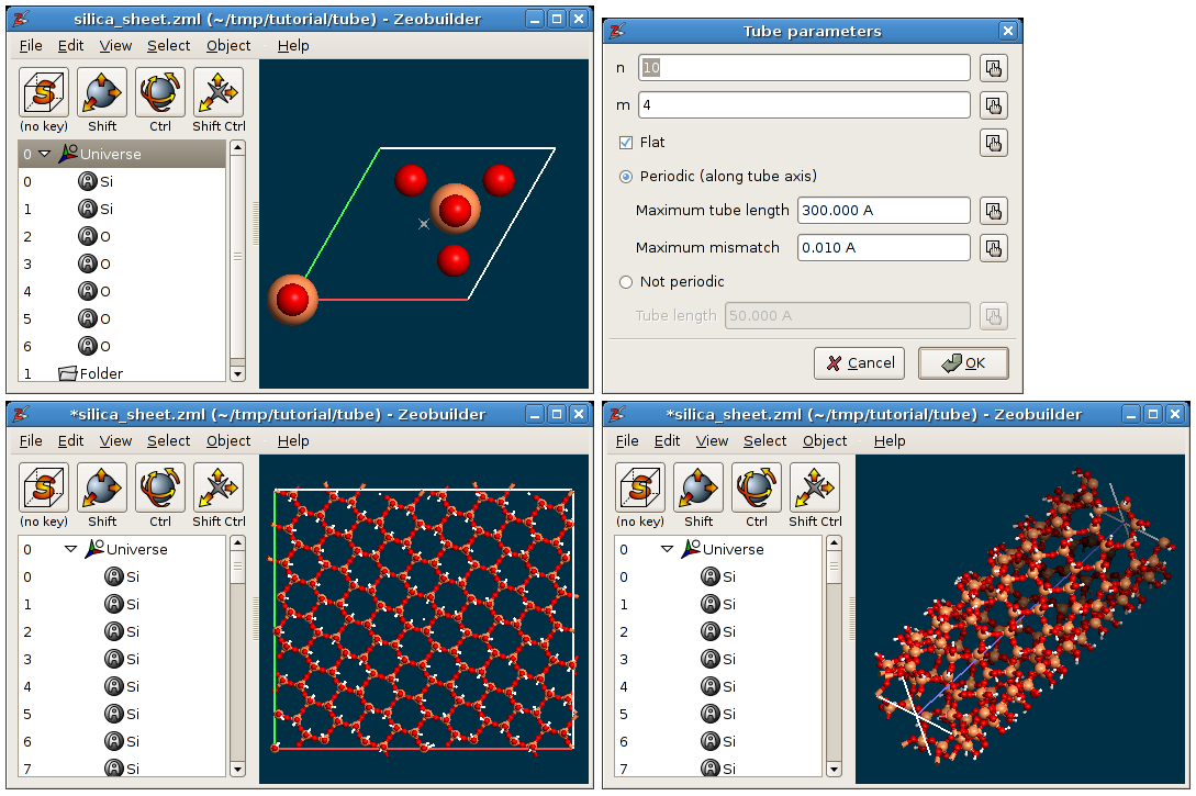
In this section we show the results of the tube tool when applied to an hexagonal silica layer: silica_sheet.zml. The tube parameters are the same as in the previous example.}}

Silica applications of the tube tool. TOP-LEFT: The orignal model, a minimal two-dimensional unit cell of a silica layer. TOP-RIGHT: The dialog window with the tube parameters. BOTTOM-LEFT: The result when the flat option is checked. BOTTOM-RIGHT: The result when the flat option is not checked.
